ROS2自动驾驶
yolo5自动驾驶
1、重要!更换U盘的操作指引
2、关闭开机自启动大程序
3、Linux基础
4、YoloV5训练集
5、自动驾驶基础调试(代码解析)
6、自动驾驶特调
7、自动驾驶原理
8、PID算法理论
9、阿克曼运动学分析理论
10、建立运动学模型
常用命令
!重要!首次使用
一、原理分析
麦克纳姆轮运动学分析
二、AI大模型
3、AI大模型类型和原理
4、RAG检索增强和模型训练样本
5、具身智能机器人系统架构
6、具身智能玩法核心源码解读
7、配置AI大模型
8、配置API-KEY
三、深度相机
2、颜色标定
10、深度相机的基础使用
11、深度相机伪彩色图像
12、深度相机测距
13、深度相机色块体积测算
14、深度相机颜色跟随
15、深度相机人脸跟随
16、深度相机KCF物体跟随
17、深度相机Mediapipe手势跟随
18、深度相机视觉循迹自动驾驶
19、深度相机边缘检测
四、多模态视觉理解
20、多模态语义理解、指令遵循
21、多模态视觉理解
22、多模态视觉理解+自动追踪
23、多模态视觉理解+视觉跟随
24、多模态视觉理解+视觉巡线
25、多模态视觉理解+深度相机距离问答
26、多模态视觉理解+SLAM导航
27、多模态视觉理解+SLAM导航+视觉巡线
28、意图揣测+多模态视觉理解+SLAM导航+视觉功能
五、雷达
8、雷达基础使用
思岚系列雷达
六、建立地图
9、Gmapping建图
cartographer快速重定位导航
RTAB-Map导航
RTAB-Map建图
slam-toolbox建图
cartographer建图
Navigation2多点导航避障
Navigation2单点导航避障
手机APP建图与导航
七、新机器人自动驾驶与调整
多模态视觉理解+SLAM导航
新机器人自动驾驶
场地摆放及注意事项
启动测试
识别调试
无人驾驶的车道保持
无人驾驶路标检测
无人驾驶红绿灯识别
无人驾驶之定点停车
无人驾驶转向决策
无人驾驶之喇叭鸣笛
无人驾驶减速慢行
无人驾驶限速行驶
无人驾驶自主泊车
无人驾驶综合应用
无人驾驶融合AI大模型应用
八、路网规划
路网规划导航简介
构建位姿地图
路网标注
路网规划结合沙盘地图案例
路径重规划
九、模型训练
1、数据采集
2、数据集标注
3、YOLOv11模型训练
4、模型格式转换
十、YOLOV11开发
多机通讯配置
汝城县职业中等专业学校知识库-信息中心朱老师编辑
-
+
首页
七、新机器人自动驾驶与调整
启动测试
启动测试
# 启动测试 ## 1. 课程内容 该教程仅用于用户想要优化调试自动驾驶功能效果时,根据自己的实际情况进行标定。 **效果可以不用标定!!如使用需要替换最新的工程包(最新的工程包主要更新了调试/标定的功能,自动驾驶的效果相差无异)** 视觉自动驾驶功能使用的是相机的RGB画面,不依赖深度信息。 使用不同的相机,相机视角中车身中轴线的位置会有所不同,所以需要标定不同相机视角中车体的中轴线 ## 2. 标定车身中轴线 ```启动相机节点 ros2 launch ascamera hp60c.launch.py ``` ```启动中轴线标定程序 ros2 run auto_drive cali_midline ``` 调整相机至正常使用位置(摄像头正朝前方,相机角度可以轻微偏下) 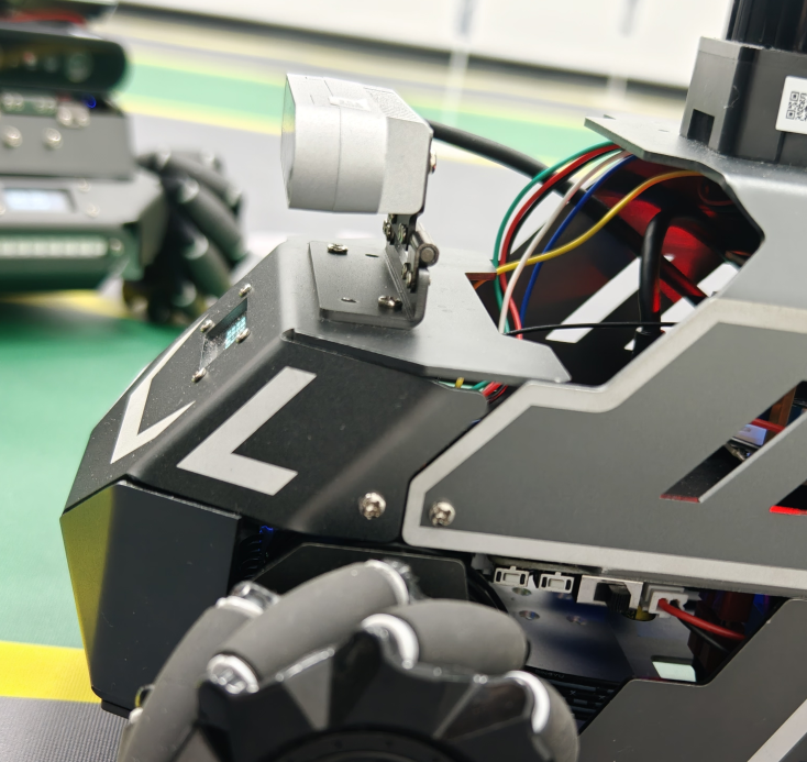 然后任意找条参考线(任何一条比较直的线都可以,这里以地图边缘线作为参考线),将车身中间对准参考线 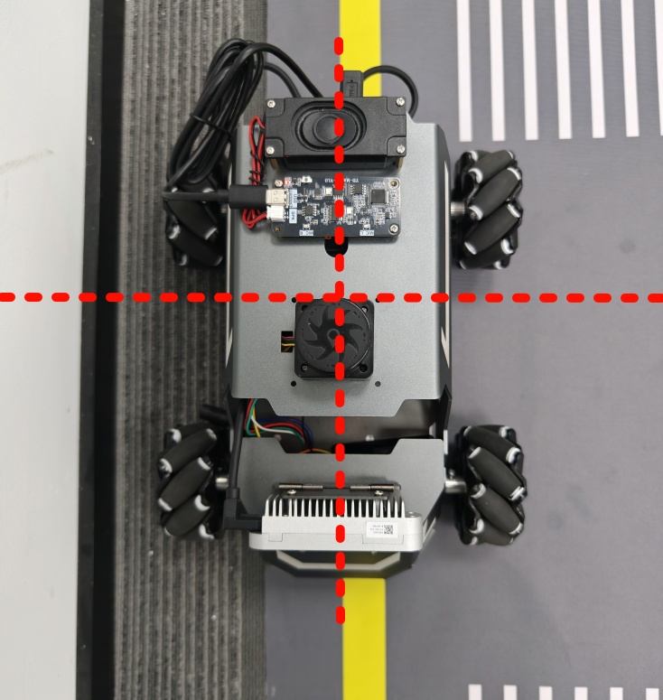 在相机的画面中我们可以看到参考线,这就是当前相机视角中车身的中轴线位置,左上角的`current mode`显示的是当前的标定模式,midline_points表示的是标定车身中轴线。 不同相机因为摄像头位置不同,车身中轴线看上去会有差异。可以发现车身中轴线在相机视角中并不是完全垂直的,实际是一条斜线。 使用鼠标依次选择中轴线的起点和终点,在参考线上从下向上任意选两个点,不需要考虑长度,后期可以通过参数调整,选择完成后终端会打印鼠标选择的起点和终点坐标。 如果对标定的结果不满意或者误点击,可以按键盘的r键重置标定状态,进行重新标定。 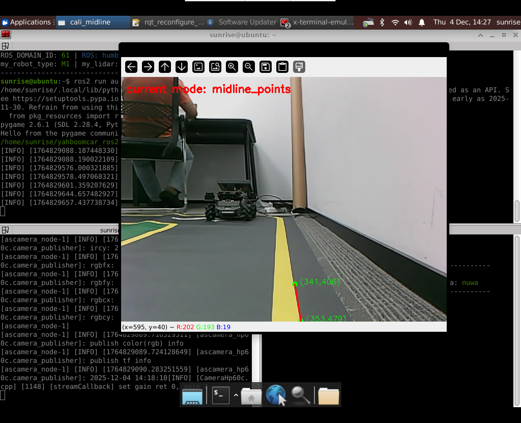 然后按键盘S键进行保存,终端会提示保存参数的文件位置。 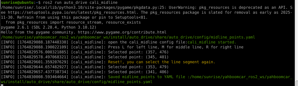 终端提示的文件保存路径`/home/sunrise/yahboomcar_ros2_ws/yahboomcar_ws/install/auto_drive/share/auto_drive/config/midline_points.yaml`是`auto_drive`功能包的install安装目录。 * **需要将里边的内容,复制到`/home/sunrise/yahboomcar_ros2_ws/yahboomcar_ws/src/auto_drive/config/midline_points.yaml`** * ## 3. 标定车道参考线 将车机放置在沙盘地图的车道中 * 车身中轴线尽可能沿车道的中心线位置 * 车身距离左右车道线的间距应该尽可能相等。 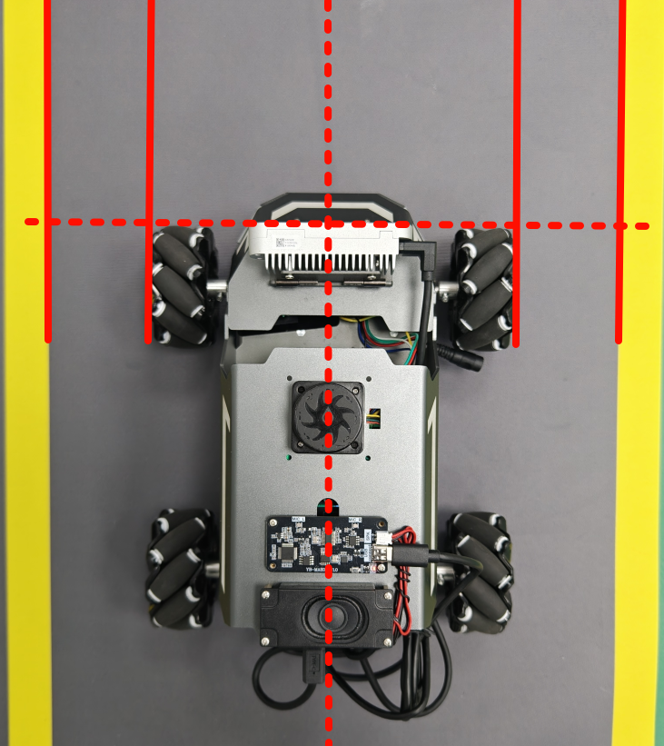 ### 3.1 标定左车道参考线 * 点击一下`cal_midline`的标题,先按键盘`R键`重置标定状态,然后按下键盘的L键切换到`leftline_points`标定模式 * 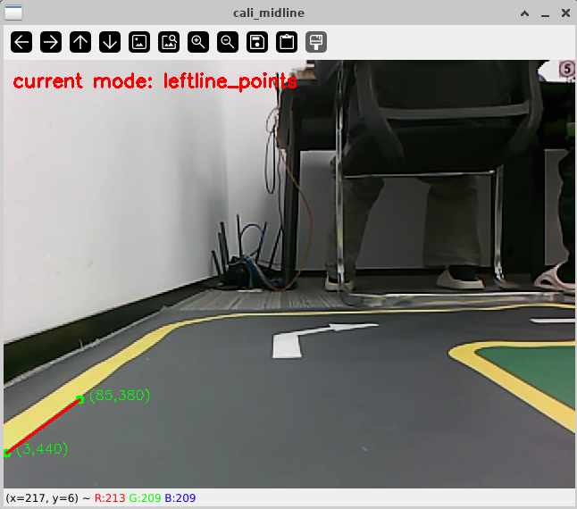 标定方法和前边类似,依次在选择左车道线的内侧线上选择起点和终点,然后点击S键进行保存,终端会打印提示信息。 ### 3.2 标定右车道参考线 先按键盘`R键`重置标定状态,然后按`K键`进入`rightline_points`标定模式 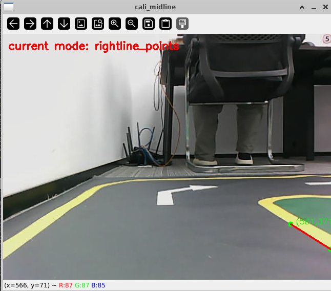 标定方法和前边类似,依次在选择右车道线的内侧线上选择起点和终点,然后点击S键进行保存,终端会打印提示信息 可以发现,当车机在车道中间时,在相机视角中左右车道线其实是两条向车道内侧延伸的线段,并且不同的相机视角中,车道线的倾斜程度也会不同。 ## 标定参数文件 * 终端提示的文件保存路径`/home/sunrise/yahboomcar_ros2_ws/yahboomcar_ws/install/auto_drive/share/auto_drive/config/midline_points.yaml`是`auto_drive`功能包的install安装目录。 * **需要将里边的内容,复制到`/home/sunrise/yahboomcar_ros2_ws/yahboomcar_ws/src/auto_drive/config/midline_points.yaml`** midline_points字段是车身中轴线的数据 leftline_points字段是相机视角左车道线参考线 rightline_points字段是相机视角右车道线参考线 midline_length字段是车身中轴线的长度(一般按默认值即可,后面教程会有调参讲解) ``` midline_points: start_point: x: 353 y: 479 end_point: x: 341 y: 406 mid_distance: - 200 - 40 leftline_points: start_point: x: 3 y: 440 end_point: x: 85 y: 380 rightline_points: start_point: x: 639 y: 420 end_point: x: 561 y: 371 midline_length: 85 ``` 标定已经全部完毕,参数修改完之后重新编译,下次运行就会使用修改后的参数, ``` cd ~/yahboomcar_ros2_ws/yahboomcar_ws/ colcon build --packages-select auto_drive ``` ## 5. 测试前准备 **注意:这个程序是在沙盘地图上运行的,个人地图需要自行调整程序,这个课程只是调试小车识别车道线的可视化情况** 基础:启动自动驾驶程序,观察车道线识别结果。 进阶:结合调试模式掌握车道线检测原理。 调整测试参数 参数路径:~/yahboomcar_ros2_ws/yahboomcar_ws/src/auto_drive/config/auto_drive_node.yaml ``` auto_drive: ros__parameters: turn_radius: 0.4 drive_speed: 0.15 angular_speed: -0.42 duration: 2.0 response_distance_1: 2900 response_distance_2: 132 cooldown_time: 3.0 DEBUG_MODE: False START_AutoDrive: True conbine_nav: False Kp: -0.4 Ki: 0.0 Kd: -0.1 Kp_1: -0.3 Ki_1: 0.0 Kd_1: 0.0 max_integral: 1000.0 min_error_angular: 0.03 offset: 10.18 initial_error: 2.55 image_size: [640, 480] ``` 测试这里需要将, `START_AutoDrive`:改成 False,小车运动的总开关,改成True的话小车运动。 `conbine_nav`:改成False , 没使用路网导航不需要打开这个。 参数修改完之后重新编译,下次运行就会使用修改后的参数, ``` cd ~/yahboomcar_ros2_ws/yahboomcar_ws/ colcon build --packages-select auto_drive ``` ### 5.1 校准零偏值 #### 小车仍然在沙盘地图的车道中保持左右居中的位置! 自动驾驶源码路径:~/yahboomcar_ros2_ws/yahboomcar_ws/src/auto_drive/auto_drive/auto_drive.py 启动相机节点 ``` ros2 launch ascamera hp60c.launch.py ``` 启动底盘 ``` ros2 run yahboomcar_bringup Mcnamu_driver_M1 ``` 启动车道线居中 ``` ros2 run auto_drive auto_drive ``` 启动成功之后会显示画面不会运动,主要测试车道线识别情况。 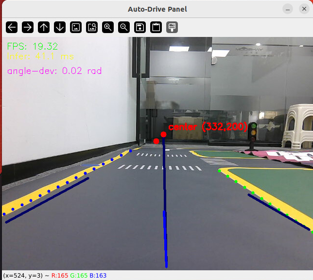 如果能看到上图中的画面的话,说明模型和程序是正常情况。其中蓝色的点表示该侧是小车的左侧,黄色的点表示小车的右侧。中间蓝色是中轴线和延长线之间的夹角。保证道路上黄线都能识别了,可以进行下一步调试。 打开动态参数调节器,RDK主控可以在虚拟机执行 ``` ros2 run rqt_reconfigure rqt_reconfigure ``` 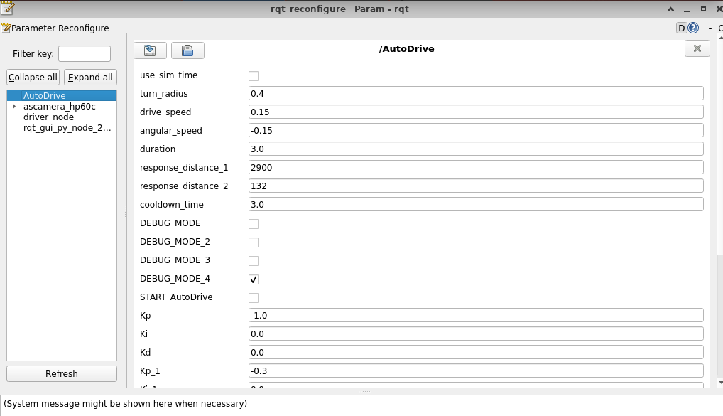 将`DEBUG_MODE_3`打开,在终端中获取左右居中零偏值`initial_error` 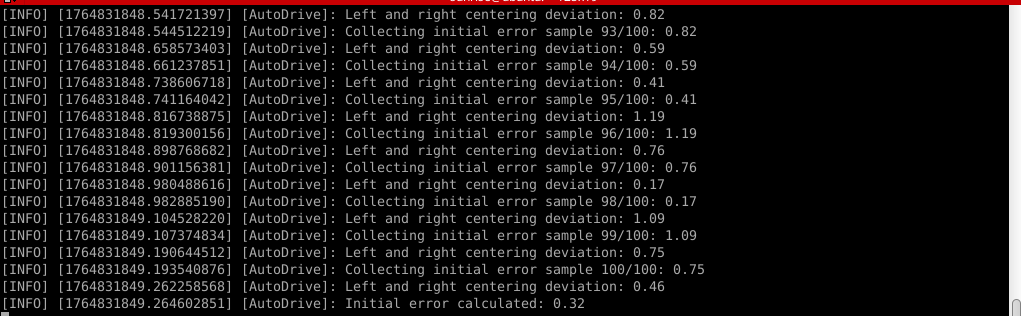 将initial_error,填入 ~/yahboomcar_ros2_ws/yahboomcar_ws/src/auto_drive/config/auto_drive_node.yaml 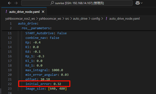 参数修改完之后重新编译,下次运行就会使用修改后的参数, ``` cd ~/yahboomcar_ros2_ws/yahboomcar_ws/ colcon build --packages-select auto_drive ``` ### 5.2 校准后预览效果 校准后再次启动程序,可以看到车道线吻合道路。 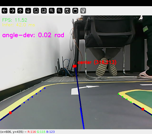 ## 6. 车道线检测原理及源码解析 ### 6.1 车道线检测原理 1. 车道线检测先由yolov11目标检测模型检测出车道线的分布区域 如果需要训练自定义车道线检测模型,参考模型训练教程 然后通过霍夫直线检测,找出检测框中最长线段,通过判断直线斜率,来划分左右车道线 车道线检测也可以通过yolov11的分割模型和OBB旋转检测模型、或其他类型的识别模型实现,但在jetson设备上实测目标检测模型的推理速度较快,实时性较好。 yolov11目标检测模型识别车道线只能检测出车道线的分布,而无法直接区分左右车道线,因为左右车道线特征极为相似,如果在数据标注阶段标注数据为左右车道线,在检测时左右车道线误判的概率会很高。所以这里采用yolov11+opencv霍夫检测结合方式进行综合判定左右车道线。 ### 6.2 车道线检测源码 yolov11推理源码: ``` ~/yahboomcar_ros2_ws/yahboomcar_ws/src/auto_drive/auto_drive/utils/yolov11_infer.py ``` auto_drive.py主程序源码: ~/yahboomcar_ros2_ws/yahboomcar_ws/src/auto_drive/auto_drive/auto_drive.py #### 6.2.1 yolov11模型推理源码 yolov11_infer.py中YOLO_MODEL是yolo检测的基类,用于扩展不同的yolo识别模型程序 ``` class YOLO_MODEL(ABC): '''模型基类Model base class''' def __init__(self): self.yolo_model=None @abstractmethod def get_infer_result(self,source): """返回模型识别结果Return the model recognition result""" pass @abstractmethod def init_yolo_engine(self): """加载模型Load model""" pass ``` Lane_Detect是继承YOLO_MODEL的子类,包含了车道线检测的各种方法 ``` class Lane_Detect(YOLO_MODEL): """车道线检测模型Lane line detection model""" def __init__(self,config_file_path:str, midline_file_path:str): with open(config_file_path, "r") as file: full_config = yaml.safe_load(file) self.config_param = full_config.get("line_detection", {}) with open(midline_file_path, "r") as file: self.point_config = yaml.safe_load(file) ---------------- ``` get_infer_result是推理图像获取车道线检测结果的方法 ``` def get_infer_result(self,source,stream:bool=True): '''获取单帧图像的推理结果Obtain the reasoning result of a single frame image''' result = self.yolo_model(source,stream=stream,conf=self.conf,iou=self.iou,rect=self.rect,half=self.half, device=self.device,batch=self.batch,max_det=self.max_det,augment=self.augment, verbose=self.verbose,classes=self.classes) return result ``` classify_lane_direction方法用从yolo的识别框中通过霍夫检测出的最长直线的斜率来辅助判定yolo框中的左右车道线 ``` def classify_lane_direction(self, frame, box, debug=False): """ 霍夫检测判断车道线方向Hough detection determines the direction of lane lines """ xmin, ymin, xmax, ymax = map(int, box) roi = frame[ymin:ymax, xmin:xmax] if roi.size == 0: return None gray = cv2.cvtColor(roi, cv2.COLOR_BGR2GRAY) edges = cv2.Canny(gray, 50, 150) lines = cv2.HoughLinesP( edges, 1, np.pi / 180, threshold=30, minLineLength=20, maxLineGap=10 ) if lines is None: return None #Filter out horizontal and vertical lines filtered = [] for line in lines: x1, y1, x2, y2 = line[0] dx = x2 - x1 dy = y2 - y1 if dx == 0: continue slope = dy / dx if abs(slope) < 0.03: # 太水平Too level continue if abs(slope) > 10: # 太垂直Too vertical continue filtered.append(line) if len(filtered) == 0: return None longest = max( filtered, key=lambda l: math.hypot(l[0][2]-l[0][0], l[0][3]-l[0][1]) ) x1, y1, x2, y2 = longest[0] if debug: px1, py1 = xmin + x1, ymin + y1 px2, py2 = xmin + x2, ymin + y2 cv2.line(frame, (px1, py1), (px2, py2), (0,255,0), 2) dx = x2 - x1 dy = y2 - y1 slope = dy / dx if slope < 0: return "left" else: return "right" ``` __draw_dotted_line方法用于将识别出的检测框绘制成可视化的车道线(虚线段) ``` def __draw_dotted_line(self, image, start_point, end_point, color=(255, 0, 0), thickness=3, dot_spacing=20): """绘制由点组成的虚线段Draw dotted line segments composed of points""" # 计算两点间距离和方向Calculate the distance and direction between two points dx = end_point[0] - start_point[0] dy = end_point[1] - start_point[1] distance = np.sqrt(dx**2 + dy**2) num_dots = int(distance / dot_spacing) points = [] for i in range(num_dots + 1): t = i / num_dots if num_dots > 0 else 0 x = int(start_point[0] + t * dx) y = int(start_point[1] + t * dy) points.append((x, y)) for point in points: cv2.circle(image, point, thickness, color, -1) return image ``` #### 6.2.2 车道线检测处理的主程序 * image_callback是订阅相机话题的回调函数,用于接收实时相机画面,然后转换成opencv格式图像后压入Lane_Detect类的缓存队列中。 * ``` def image_callback(self, msg: Image)->None: '''ros图像回调函数,将ROS图像转换为OpenCV格式,加入处理队列中 The ROS image callback function converts the ROS image to OpenCV format and adds it to the processing queue. ''' cv_image = self.bridge.imgmsg_to_cv2(msg, desired_encoding='bgr8') self.lane_detect.put_image(cv_image.copy()) ``` handle_lane方法负责从Lane_Detect类的缓存队列中取出图像画面,进行加工处理,处理流程为:1.从队列取图像帧 → 2. 模型推理得到车道线检测结果 → 3. 分类左右车道候选框 → 4. 筛选最优左右车道框 → 5. 可视化结果 → 6. 循环等待下一帧 其中分类左右车道线的程序如下: ``` for res in results: boxes = res.boxes # 单帧的所有检测框(xyxy格式:xmin, ymin, xmax, ymax) if self.DEBUG_MODE: frame = res.plot() # 调试模式:绘制所有检测框到图像 if boxes is not None: for i in range(len(boxes)): box_coords = boxes.xyxy[i].tolist() # 单个检测框的坐标(左上角+右下角) # 关键:调用分类函数,判断该框属于左车道/右车道 lane = self.lane_detect.classify_lane_direction(frame, box_coords, debug=self.DEBUG_MODE) if lane == "left": left_candidates.append(box_coords) # 加入左车道候选 elif lane == "right": right_candidates.append(box_coords) # 加入右车道候选 def handle_lane(self)->None: '''处理车道线识别的检测结果Processing lane line recognition detection results''' while True: try: frame = self.lane_detect.image_queue.get(timeout=0.1) except queue.Empty: continue infer_start = time.time() results =self.lane_detect.get_infer_result(frame, stream=True) #初始化默认值Initialize default values left_box = None right_box = None left_candidates = [] right_candidates = [] for res in results: boxes = res.boxes # 检测对象边界框Boxes object for bounding box outputs if self.DEBUG_MODE: frame = res.plot() if boxes is not None: for i in range(len(boxes)): box_coords = boxes.xyxy[i].tolist() # 获取边界框坐标 (xyxy格式: xmin, ymin, xmax, ymax) Get the bounding box coordinates (xyxy format: xmin, ymin, xmax, ymax) lane=self.lane_detect.classify_lane_direction(frame,box_coords,debug=self.DEBUG_MODE) if lane=="left": left_candidates.append(box_coords) elif lane=="right": right_candidates.append(box_coords) if len(left_candidates)>0 : left_box = max(left_candidates, key=lambda box: box[3]) # 选择最靠近底部的边界框(ymax最大)Select the bounding box closest to the bottom (with the largest ymax). if len(right_candidates)>0: right_box = max(right_candidates, key=lambda box: ((box[2] - box[0])**2 + (box[3] - box[1])**2)**0.5) frame=self.__handle_lane_detect_result(left_box,right_box,frame) infer_end = time.time() self.frame_count_1 += 1 curr_time = time.time() time_diff = curr_time - self.prev_time_1 if time_diff >= 1.0: self.fps_1 = self.frame_count_1 / time_diff self.frame_count_1 = 0 self.prev_time_1 = curr_time cv2.putText(frame,f"FPS: {self.fps_1:.2f}",(10, 25),cv2.FONT_HERSHEY_SIMPLEX,0.6,(0, 255, 0),1,) infer_time = (infer_end - infer_start) * 1000 cv2.putText(frame, f"Infer: {infer_time:.1f} ms", (10, 45),cv2.FONT_HERSHEY_SIMPLEX, 0.6, (0, 255, 255), 1) cv2.imshow("Auto-Drive Panel", frame) cv2.waitKey(1) ```
admin
2025年12月7日 10:30
70
转发
收藏文档
上一篇
下一篇
手机扫码
复制链接
手机扫一扫转发分享
复制链接
Markdown文件
Word文件
PDF文档
PDF文档(打印)
分享
链接
类型
密码
更新密码
有效期
AI